The job has filled, thanks for the interest.
So.... my firm (whose name I tend to leave off this blog) is seeking a highly motivated proffesional to move to our foriegn office to provide (I hate to say it) 2D Autocad management, and...... BIM & Revit management. We have recently launched our first Revit projects in the office (see earlier blog post), and the staff is very excited to begin using this new tool. Right now we have architects, interior designers and structural engineers working in Revit in our overseas office. The office is composed of highly motivated staff working on some of the largest and most interesting projects in the country. The ideal canidate should have experience in managing 2D CAD, experience with Revit and be highly motivated to work with a BIM implementation team to move our 700 person firm towards 100% use of BIM by.......... (trust me its soon) :).
Please feel free to contact me via AUGI private message, or contact the firm directly.
Cheers,
-R
Tuesday, December 05, 2006
Follow-up to AU class on roofs
Hey all, had a great time at AU in Las Vegas! At least one picture of me and several other folks have made it on to the AUGI website. I got to attend Scott Brown and Scott Davis' class on creating roofs. I don't usually do straight forward tips & tricks but here is a little of my own follow-up for their course.


 Once the first group has been arrayed you can go back and modify the mass, and create a new roof by face. Group the new roof, then you can select your remaining groups and change the group type to match your new group.


During the class the guys showed how to create a roof using a mass element, this is handy for unique conditions, or repetitive unique condidtions, like roof crickets, or warped/sloped flat roofs. In their example they used a blend to create a more unique condition, however for my little tutorial I used some blander mass shapes to create my roofs.

I started by creating a mass object that represents the reptitive portion of my roof.
Then I created a roof by face and grouped the roof. From there the group can be arrayed.


 Once the first group has been arrayed you can go back and modify the mass, and create a new roof by face. Group the new roof, then you can select your remaining groups and change the group type to match your new group.


The advantage of this methodology is that for a repetitive roof element you only have to manage one mass object, as opposed to defining multiple mass objects. You can even rotate, move and mirror the group throughout a model. You can't include the mass object in the group, as the roof by face command can't re-create the roof object, it looses its assoication. If you're not going to need your old roof object make sure to delete the group. While groups can sometimes be problomatic with large number of elements, you should not encouter too many problems with some simple roof elements. This technique should prove especially useful for any project with large repetitive roof structures.
Sunday, November 26, 2006
Friday, November 17, 2006
Foriegn Training


Ahhhh!!!! Since the beginning of the month things have just been crazy! I was in one of our other stateside offices to give advanced family training to our MEP engineers who are starting to explore Revit systems, and now I'm in our foreign office for about a week to do Revit training with a 20 person team to kick off a new Revit (and first) Revit project here. Thankfully I'm not alone trying to teach 20 people, but the experience has been great! We already have them working in their project files! I've attached a couple of my very poor night pictures, so if you can figure out what its a picture of, you might have chance of determining what country I'm in! In any case I'm back in the states next week (Tuesday) then Thanksgiving, and then AU! I'm looking forward to AU as an intense vacation!
One of our biggest problems in hopping the pond to our foreign office is that we have very little custom Metric content. Though we've very quickly got a project template started for them, and we are working on a titleblock, buts its all very fast and very insane. Before leaving I will be teaching my intensive family training course to users who hadn't even touched Revit until this past week!
Cheers,
-R
Friday, November 03, 2006
Philly Revit Users group
Philadelphia Revit Users |
Visit this group |
Tuesday, October 31, 2006
Integrated Practice
This morning I had a chance to go to an AIA breakfast on Itegrated Practice (IP). It was led by Norman Strong, FAIA. Most of the people in attendance were prinipals, owners and managing partners of architectural firms from around our area. The great thing about this talk was that it was focused on how BIM allows IP, and how in reality to fully immplement BIM, and your BIM tool of choice, a firm must realize that what is required is a change in the way we practice. Firms cannot rely on their IT person or deptartment to immplement "BIM" IT can certainly help and support, and lead the training on a specific tool. However, should we fail as professionals to realize that we must alter our approach to practice then "BIM" will never be more than a glorified CAD package. An interesting point made by one of the other speakers at this morning's engagement was that when the industry transitioned from hand drafting to CAD the "experts" promised 3%-5% improvement on our productivity, however when you do all the math, we haven't really improved our efficiency. This can lead to two conlusions, a) either CAD did nothing to improve our efficieny, or b) as business people we managed to find a way to give away any improved value/productivity that resulted from our adoption of CAD. This is extremely troubling. Not only do we need to determine how to change our practice, but in doing so we also need to determine how to maintain our value, while sharing risk & reward, so that our clients and consultants see the value we can and do provide.
-R
-R
Monday, October 30, 2006
Yet another Blog graces my links list :)
Yes, if you are a regular reader of Revit & BIM blogs, you probably already know about James Van's blog. He was nice enough to leave me a comment, so I'm returning the favor by linking to his blog, "All Things Bim".
Thanks to the new RevitCity 2.0 for also posting a link to my blog!
-R
Thanks to the new RevitCity 2.0 for also posting a link to my blog!
-R
Thursday, October 26, 2006
Tracking Your Families
I thought I would share a technique we've appplied to all of our family creation which helps a little bit with keeping track of families, and knowing where they came from. In any new family that gets created at my firm, or if a family is downloaded from a site like RevitCity or AUGI, we ask that the users add three text parameters under the "Identity Data" heading;
- Version Number
- Source
- Author
In the case of creating a new family in the firm, version number would typically start at 1.0, Source would be the firm's name, and Author would be the author's name. For families that are produced by contracted consultants, Source would be the consultant's name, and author the employee of the consulting firm that creates the family. For downloaded content, source would be the website and author would be whatever the username is of the contributing "original" author, or as best can be determined. As part of integrating these three parameters with the process of creating new families we are planning/hoping to add them to all family templates so that the end user merely needs to be concerned with filling the parameters out. When creating new families in our firm we also require end users to provide a description, an assembly code (when it makes sense) and a keynote (also when it makes sense).
Why go to all this trouble? The tracking parameters help us to know where a family came from if it is in circulation. If we have the author and a version number we can to a certain extent more easily track down problems. If the author still works for us, we can just go back to them, version number helps, because there might be a more recently updated family that addresses the problem the user is having with the family. By requiring the descriptive data we are "future proofing" ourselves as we use E-Specs more, or if we work with contractors or other consultants where this type of data can be important, or if we figure out new and innovative ways to make use of the data.
We also include a version number in our Project Template file, which exsists as a project parameter under Project Info, no end user is ever going to bother touching it, and most people probably won't ever notice it. However, once again, if there is a problem with the template we can know what version the template is, furthermore everytime the template is updated we have an excel file where we track the version numbers and changes, thus, we can know what might be missing from an older template and or what needs to be updated to resolve an inherent problem with the template.
There is one downside to the "versioning" of our families, when reloading, even when "overwrite parameters of existing types" is selected the version number does not always update, which is rather unfortunate, as it makes it harder to track what version of a family is loaded into a particular project. Hopefully in the future Autodesk will provide some resolution to this issue.
Thanks for reading,
-R
Wednesday, October 25, 2006
New Search Tool
Google has released a new custom search tool. I've added it to my blog to the left. Right now it searches a very limited number of websites. Over the next few days (ahhh, weeks... :) ) I will try to tweak it. I've given it a limited number of Revit related keywords which are supposed to help with the search results. If you give it a try leave a comment and let me know what you think. If you post a url of a Revit website I should be searching it will make it easier and faster for me to add to the search.
If you're a fellow Revit or BIM blogger (and I know who some of you are) and are interested in collaborting on building the search, and including it on your own blog, drop me a comment, or if I've already been in touch with you via other digital communiques contact me that way.
Cheers,
-R
If you're a fellow Revit or BIM blogger (and I know who some of you are) and are interested in collaborting on building the search, and including it on your own blog, drop me a comment, or if I've already been in touch with you via other digital communiques contact me that way.
Cheers,
-R
Monday, October 23, 2006
Improving Family Performance
There is a very simple method that can be employed to improve family performance when loaded in a project, the technique makes it much easier for Revit to "draw" views as it doesn't have to calculate anything with regards to cutting through the family's geometry. Using symbolic lines to represent what the family looks like in a specific view type (plan/R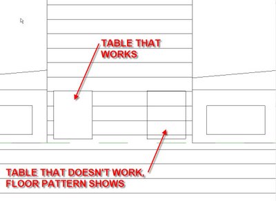 CP, elevation front/back, elevation left/right) with visibility settings set to turn off 3D geometry, allows Revit to automatically render the symbolic lines in the particular view, and ignore the 3D geometry. Revit doesn't have to calculate what the family might look like if it is cut by the view plane, or even if the family is being cut by the view plane, it simply displays the symbolic geometry. However there is one slight hitch, if you're working in any type of 3D family, and draw symbolic lines, when you place the family into a project you'll "see" right through the family! See the image to the right.
To fix this problem you need to create a detail component and nest into your 3D family. Detail components (2D geometry only) allow the use of filled regions (which thankfully can block patterns!). If you create a parametric detail component with a filled region, you can then nest it, and attach its parameters to the parameters of the 3D family. Once this is taken care of you can succesfully load the family into a project and get the results of the table on the left.
I highly reccomend creating a rectangular detail component with a filled region, with the lines set to "invisible", you can then use this component in a variety of situations. If you do not want the filled region to have a pattern or color, make sure to set the type properties of the filled region to "no pattern" and not a solid fill color. If however you want a material pattern you can choose whatever you like. You may also want some filled region detail components for other common shapes like circle, L, etc...
Setting the parameters to instance based will give you shape handles when the component is loaded that can be quickly grabbed & locked. These filled region detail components can be handy for detailing in project views too, rather than having to always create filled regions every time you need one. Instance parameters will make it so that you don't need multiple types.
 CP, elevation front/back, elevation left/right) with visibility settings set to turn off 3D geometry, allows Revit to automatically render the symbolic lines in the particular view, and ignore the 3D geometry. Revit doesn't have to calculate what the family might look like if it is cut by the view plane, or even if the family is being cut by the view plane, it simply displays the symbolic geometry. However there is one slight hitch, if you're working in any type of 3D family, and draw symbolic lines, when you place the family into a project you'll "see" right through the family! See the image to the right.
To fix this problem you need to create a detail component and nest into your 3D family. Detail components (2D geometry only) allow the use of filled regions (which thankfully can block patterns!). If you create a parametric detail component with a filled region, you can then nest it, and attach its parameters to the parameters of the 3D family. Once this is taken care of you can succesfully load the family into a project and get the results of the table on the left.
I highly reccomend creating a rectangular detail component with a filled region, with the lines set to "invisible", you can then use this component in a variety of situations. If you do not want the filled region to have a pattern or color, make sure to set the type properties of the filled region to "no pattern" and not a solid fill color. If however you want a material pattern you can choose whatever you like. You may also want some filled region detail components for other common shapes like circle, L, etc...
Setting the parameters to instance based will give you shape handles when the component is loaded that can be quickly grabbed & locked. These filled region detail components can be handy for detailing in project views too, rather than having to always create filled regions every time you need one. Instance parameters will make it so that you don't need multiple types.
Wednesday, October 18, 2006
New blog (though you've probably already seen it)
Because I like what she has to say, I've also joined the chorus of fellow Revit bloggers and added Laura's blog about using Revit in the contracting world to my list of links. Thanks to David & Steve where I found her, don't know who was the first one to pick up on her blog. Hopefully my firm can do some work with Tocci, seeing as we have a Boston office....
Here's to Revit!
-R
Here's to Revit!
-R
Tuesday, October 17, 2006
Reference Planes in Families
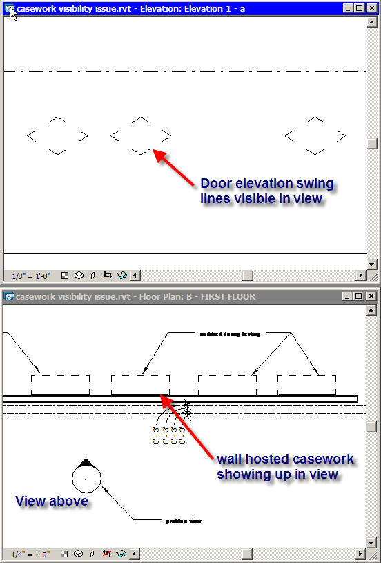
When creating parametric families we've found that the best way to control the dynamic geometry is to create a skeleton of reference planes to which dimensional parameters are attached. Once the skeleton works as expected we create geometry that we attached and lock to the reference planes. However recently we've discovered one minor issue that family authors should be aware of when using reference planes in creating families. On several occasions we've had symbolic geometry randomly showing up in views where it shouldn't. For instance an interior elevation had casework door elevation swing lines showing up when the cabinets were on the other side of the wall (see figure to right). Or, we've had door elevation & plan swing lines show up in views where the door isn't visible. The culprit in all cases has been "extra" reference planes that aren't being used in a family. What makes it even harder to track down is the offending reference planes are often in nested families. In both cases of the casework doors and regular doors it was a piece of hardware that was causing the problem. The hardware was created a "generic model" and the template used included some pre-defined reference planes that weren't required for the handle, because the reference planes were pre-defined they couldn't be deleted, and the author simply left the planes where they were. In the case of the handle, even though the planes were only a couple of feet away (see the figure bottom right) from the origin the handle was so small that it caused problems. In this case  the solution was to move the reference planes in extremely close to the geometry so as to stop causing problems.
Cheers,
-R
 the solution was to move the reference planes in extremely close to the geometry so as to stop causing problems.
Cheers,
-R
Wednesday, October 11, 2006
Construction Administration & Blog upgrade
You might notice a few differences, I took the plunge and upgraded my blog to the current Beta, I like it a little better, and I hope you do to. If you're not using IE or Firefox you may have problems viewing the blog, sorry folks, blogger says they're working to fix it all.
Construction Administration (CA) of a Revit project seems to be becoming a hot topic. There have been a couple of threads, some new, some ressurected, showing up on AUGI. Currently because of our average project sizes we are reccomending that projects should expect to export a full set of DWG documents when the Construction Documentation (CD) phase has ended. Generally we've found that while plans export very well, and sections generally do, we find that we need to do clean-up on elevations, and some general housekeeping on the other views. While on a very large project, it might take week to do this, we think its worth it. So far, from what we've seen when you have a large revit project, on a tight site, with a tight schedule, and unforseen conditions (that never happens right ;) ), Revit just doesn't lend itself to quickly producing RFI sketches and addendum. We want to keep the Revit model involved, but at the same time we need to face the realistic needs of our project teams.
Furthermore, the other kink in Revit is not being able to have a view on more than one sheet, this makes it very hard to issue an addendum sketch, and have the same drawing on the original sheet. There are some lenghty dicussions on AUGI about this topic, but suffice is to say, work arounds are just sometimes a pain. CA is fraught with enough difficulties, we don't need to make it harder for our own staff.
Hopefully Autodesk will find time to address this portion of Revit's use, and of course we will continue to encourage them to do so. :)
Ciao,
-R
Thursday, October 05, 2006
Family Clinic (learning to create parametric families)
So the other big thing that happened before going to San Fran & the west coast was that I held an intensive day long advanced family creation clinic (my pastor thought this was a little sketchy sounding ;) ) based around my firm's family standards as defined by the family outline specification that was one of my first blog posts. The training session started with about an hour and half going through a power point that I created that illustrates best practices for creating solid parametric families that are easy to diagnose and distill; as long as everyone follows the rules such as; always name reference planes, and categorize your parameters, don't let them all sit under the "other" heading. There are more.... :) but you gotta come work for us first ;).

After the powerpoint, which was interspersed with live Revit demos to illustrate various points, we moved on to creating a family. Here's a pic of what I told them they would have by the end of the day.
Specs:
2 pick family with arrayed nested cabinet family that can be user modified, doors are also nested and interchangeable. As a bonus they're challenged to write the formula that will limit the number of cabinet instances so that they don't extend past the overall length (yes I did write the formula as proof of concept).
All of them did it (I had about 8 people in the class, course my CIO was reading his e-mail, didn't see Revit open on the laptop ;) ). It was a fantastic training session and we covered just about everything related to families. Workplanes, subcategories, parameters, formulas, shared & nested families, visibility settings, shared parameters, keynotes, and of course general best practices on building complex families. Everyone felt that the course was a great success, and I was very happy with the results. I was very fortunate in that one of my co-workers in the course is a note taking nazi and she has provided excellent written documentation of what we did, making it much easier to make it repeatable and tweakable.
At the start of the day I provided them with a CD that included the power point, a PDF synopis of key points to remember (printed too), the required family templates, keynote file, shared parameter file, excel file of the firm's additional subcategories, and examples of the finished families, and the doors (I pre-made them for them). My favorite part though was that I was also able to include progressive copies of the families. By setting the number of back-up copies to 250 I was able to create a sequence of files by saving after every major action as I created the families. In the end I have 14 sequential files of the base cabinet, they proved very useful as I had a latecomer to the class, and I was able to catch him up ASAP by simply opening one of the 14 files and he was ready to go.
All in all this was a great experience and I was very satisfied with the results, and everyone who participated thought that it was great (though a long day). Now though, I know where I can break up the course to do it in shorter smaller parts. In addition to teaching the course internally, I hope to take it public at some point (with some modifications ;) ). I look forward to doing it again and perfecting it. :)
Cheers,
-R
Saturday, September 30, 2006
Return from the dead.... BIM planning!
So... I've been AWOL for a month, between deadlines & a wonderful vacation to San Francisco and Napa Valley I was a bit busy. :). However lots has been going on in the world of BIM at my firm.
First! Well there was stuff here, but it went away, if you were lucky enough to read it, well you were lucky. If not, sorry, come work at my firm, you'll learn even more.
substitue text, not quite as interesting sorry:
We continue our efforts to document our procedures and how to use Revit on a project. We have developed written documents that help a project team to determine if a project should be done in BIM & Revit. Once that decision is made we've developed documents meant to assist the project team in getting started, and things they should do as they're project moves ahead. We are also working on developing in house resources to better share ideas, tips and techiques between all our offices, that encourage the participation of everyone, and not just the BIM team.
More to come this week... I have some other great stuff. If you all are curious I will be at AU this year (my first :) ) needless to say I'll be in Revit classes, as will several other folks from my firm, looks like we'll have about 4-5 people at AU.
Cheers!
-R
Wednesday, September 06, 2006
Some advertising and new family development
Since at least one blogger recently mentioned that he stops in from time to time, I thought I would put up a few of the blogs I read on a regular basis as a thank you.
Daniel recently gave me a shout out, so if you didn't get here from there, go visit him: Revit Job Captain
David's Blog is great! I don't have to worry about coming up with cool little tips and tricks cause I always know I can stop by his site, or send a user there to learn something. Revit Beginners
I wish Shaun and Mike would be a little more consistent (but I probably shouldn't talk :) ), but when they do post something its usually pretty good. Revit Family Man
And of course Steve Stafford (who already has two links in the side bar) if you're using Revit and don't know who Steve is, then dude or dudette, you need to read more and join AUGI!
I'm working on cooking up some good stuff right now, as is the whole BIMplementation team, hopefully I should have some good stuff to report on in a couple weeks.
Currently I'm working on some pretty sweet parametric elevator families that make use of both nesting & shared families. The biggest issue I'm having though I can't completely control the visibility of objects the way I'd like to unless I throw a bunch of visibility switches into the type parameters, which given its an elevator, would only make it ever more complex! I've shared/nested the elevator cab with a type parameter so we can have couple of basic elevator frameworks that a team/user can put in whatever type of elevator cab they need, double door/single door, some other custom cab.... My current cabs do however allow the user to choose either centered door or offset door with a flip of a switch. I debated about having one cab that you could also choose if it was a double or single door, but decided it was adding an uneccessary level of complexity as I would has to do alot of controlling of voids to move them out of "cutting range". I know that you can do this, but the old fashioned 3D modeler in me isn't quite sold on having random unused pieces of geometry hanging around in families (seems like a good way to potentially slow your model down for no good reason).
I've also included a fair number of shared parameters in the elevator family(s) so that essentially a project team will be able to create an elevator report, that shows exactly what they need for each and every elevator in their building. All the dimensions and information that architects would be concerned about. I know some of this info could be included by just creating new parameters in a schedule, however this opens the possibility of inconsistency from project to project. Whereas if we build the info in the families from the get go it is much easier for the end users who perhaps are not, and never will be super duper Revit experts, and in a 600 person firm, we are never going to have super duper experts for every project & project team as we move to 100% BIM. Therefore, we need to make these easy and simple!
Cheers,
-R
Monday, August 21, 2006
Mathmatical Forumlas in Families
This post actually comes from my friend David who orginally posted it on AUGI. Since I can never keep track of items in forums I decided to repost it here. Enjoy.
---------------------------------------------------------------------------------------------
Not a math genius, or even a Revit one (or else I would have spent way less time figuring this out) but I think I have a way to deal with the "Inconsistent Units" error message. I had a problem in which I needed to calculate the arc lengths of some segments. I used a slightly different method (from previous posters, Ed), but the critical piece (the "Inconsistent Units" error) was the same. In the end I realized that Revit, just like my Chemistry teacher, expects me to cancel units in my equations. Even though WE know that the units cancel out (and that Pi is unit-less) Revit is quite literal: Pi is a number, arc length is an angle, radius is a Length and so on. It cannot see how you could possibly relate them with mathematics.
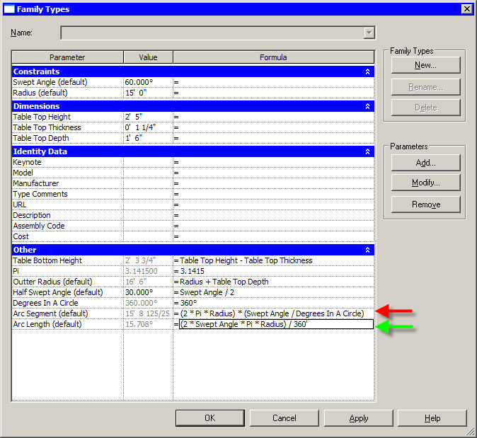
 As you realized, you can trick Revit in a couple of ways, I am attaching a screen shot of two examples. In the first (Green Arrow) I added incorrect units to values. You can see this makes the equation "work" but yields an answer in degrees whilst we want feet and inches. The second way, (red Arrow) is to break up your equations so that portions of them yield "unit less" values, and then combine them at will. Of course you could get this functionality in a single equation, so long as your units all cancel to yield whatever parameter type you are supposed to have.
---------------------------------------------------------------------------------------------
Not a math genius, or even a Revit one (or else I would have spent way less time figuring this out) but I think I have a way to deal with the "Inconsistent Units" error message. I had a problem in which I needed to calculate the arc lengths of some segments. I used a slightly different method (from previous posters, Ed), but the critical piece (the "Inconsistent Units" error) was the same. In the end I realized that Revit, just like my Chemistry teacher, expects me to cancel units in my equations. Even though WE know that the units cancel out (and that Pi is unit-less) Revit is quite literal: Pi is a number, arc length is an angle, radius is a Length and so on. It cannot see how you could possibly relate them with mathematics.
 As you realized, you can trick Revit in a couple of ways, I am attaching a screen shot of two examples. In the first (Green Arrow) I added incorrect units to values. You can see this makes the equation "work" but yields an answer in degrees whilst we want feet and inches. The second way, (red Arrow) is to break up your equations so that portions of them yield "unit less" values, and then combine them at will. Of course you could get this functionality in a single equation, so long as your units all cancel to yield whatever parameter type you are supposed to have.
Wednesday, August 16, 2006
keynotes
This will be a short post... Not enough time in one day to get everything done.
We are excited by the prospect that the new keynoting feature that Revit 9 brings to the table, however we are quickly realizing that in a firm of 600 employees it presents certain problems that one might not typically run into in a smaller office environment. For instance, given that we have 7 offices or so, needless to say there are a number of project managers and architects who have their own thoughts and opinion regarding how drawings should be noted and what notes should or shouldn't include. Therefore we must take the default keynote list that ships with Revit and evaluate it against what our PM's expect, and the contents of our standard outline specification.
The way keynoting works is a complete reverse from how architects have typically noted their drawings. In the past we of course drew some lines (or extruded some shapes, whichever) and the added notes later to describe what the "lines" represented. Now, with keynoting, done correctly, all the thinking needs to occur ahead of time, as the object is being modeled. Of course its possible to use more generic keynotes early on before the detailing of a building has been completely thought through (place holders as it were) (see Daniel Hughes' recent post) but needless to say this is still a new way of thinking regarding documenting a building. This is where it is important to make sure that above all else Project Mangers understand the process of BIM, even if they don't necessarily know everything about how to use a specific piece of software, BIM training.
The other opportunity that the keynote feature provides is a way to close the loop of Revit -> Especs -> Revit. Now it will be possible to model the building, extract the information from the building model to create an outline specification, have the spec writer further develop the final project specification, and then modify the keynote table to match the final specification. This shows us that for each project we need to expect to make a local copy of the BH typical keynote file, so that each project can modify it as needed per project specifics.
One last thing that keynoting now allows, 11th hour modifications to a drawing set without having to actually change the model or its geometry. For instance say you have a project where you've specified slate roof shingles, at the last moment its determined that you need to use asphalt shingles instead. In most cases you would probably want to actually change the model, but now if the shingles are keynoted, all you really need to do is modify the keynote of the roof, if for some reason you don't want to actually change the model at that time.
Cheers,
-R
Tuesday, August 01, 2006
training BIM
We recently had a two day retreat where everyone involved with implementing BIM accross our U.S. offices got together to really start laying the ground work for a firm wide push to adopt the design philosphies of BIM, and therefore the use of Revit. Our CEO has already drawn the line in the sand, he expects us to be 100% BIM in 3 years, this is HUGE, the first reaction is probably one of shock, consider our market sectors for a moment, health care, higher ed, mixed use development, high end multi family residential, sci tech, k-12, and commercial/retail. That is a variety of project types and project requirements to move into a BIM mode of production. However, the second reaction should be "thats HUGE" not because of the mamoth task ahead of us, but because we have complete corporate leadership buy-in as far moving our practice to a BIM based practice. Not only that, but our CEO and other key leaders in the firm understand conceptually what it means to be practicing BIM, and why the investment in transistion to a program like Revit is worth it.
So; that is what our 2 day meeting was about, creating a full implemntation plan for our firm, what are our priorities, what do we need to do, who are we going to need to do it, how much time is it going to take. This way we can tell our leadership what we need to full fill their goals, and they can endorse it, and help to make sure it happens. One of our great advanatages we feel moving forward is that most of the people who were at our 2 day meeting are practicing architects and engineers, this train isn't being driven by IT, IT is enabling us, and supporting us, but at the end of the day the implementation and use of BIM is being pushed forward by people who are working on projects everyday!
This brings me in a round about way to my original intent of this post. In our 2 day meeting we talked about training. During that discussion we realized that in the process of moving our firm to BIM/Revit, there are two different things we need to train people on. Users need to learn how to technically use Revit, but at the same time people need to learn what BIM is. BIM is not Revit, Revit is a BIM tool, to practice the theories of BIM a user does not have to be working in Revit, they could be in sketch-up, or archicad, or excel, the point is that BIM needs to be a philosphy of practice that affects how we design, how we deliver value, how we practice our proffession. To us, it is important to clearly seperate BIM from Revit, Revit may not be here forever, but we strongly feel that BIM is where our proffession(s) have to go, we can't look back, we must press ahead!
To that end I've created a simple vignette that illustrates the concept of BIM, without using Revit! (oh and say hi! to Mrs. Robert, :) )
Sunday, July 30, 2006
Vertically Stacked Partitions

On several occasions I've had a new Revit user "discover" Revit's vertically stacked partitions. They usually think this is the quick and painless answer to all their problems with exterior walls; changes in materials, water tables, etc... I usually then have to patiently explain why, even though they are conceptually a good idea, vertically stacked walls are in fact the devil incarnate (per our Autodesk Revit contacts) and that in the long run these wall types tend to cause more problems then they help solve. Though I have been told they are perfectly good and useful at an early conceptual phase.
However, I have to admit that just the other day I had an inspiration for where vertically stacked walls could in fact be very useful (though I don't make any promises because I haven't been able to use this theory yet). The idea cam up because a user was scheduling material quantities and I pointed out that numbers for GWB can be a bit hazy because of the way Revit typically handles both interior & exterior walls, and quite often there is alot more GWB in your model then the contractor will actually build.

It was then that I realized that we could use a vertically stacked partition for an interior wall where the GWB needs to only go up the ceiling (or just a little past). The image to the right shows my example. The left most wall is a typical partition with GWB on both sides of a mtl stud. In this case it goes all the way to the bottom of the floor system above. The wall in the middle is just metal studs, and the wall on the right is a vertically stacked wall type composed of the two walls to the left. In this cas the vertically stacked partition is named "Inteiror Stacked Wall - 8' Ceiling", the GWB partition is set to a fixed height of 8'- 6" so that there is a GWB overrun above the ceiling height. The metal stud partition is set as variable so that in section the structure appears to go all the way to the floor system above.
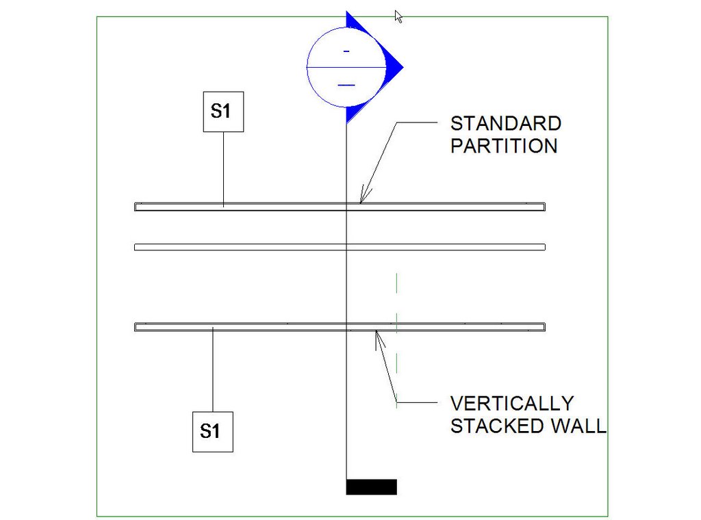 In a situation like this you would have to have a Vertically Stacked wall type for each ceiling height condition you have, however typcially a partition like this would be used in offices with no privacy concerns or light commerical; where you probably won't have very much ceiling varation. What is also nice is that even if you have multiple stacked wall types (for different ceiling heights), as long as you use the same basic wall type ot build it; in plan they will all tag the same!
Tuesday, July 11, 2006
Mapping a Facade
So far in a number of our projects, we find that conceptual and early schematic design usually involves still using 2D cad to either explore design options, or because the staff doesn't have the Revit experience yet (and may never :) ). We recently ran through an exercise on a project in that situation that I thought was useful.
This project had the elevations drawn in ACAD, by the designer (base on Revit elevations).
Openings will have to be cut in the stud back up wall, and custom mullions will need to be used on the nested C.W. for where the glazed portions occur.
Custom mullions must be used on the nested curtain wall, otherwise it is not possible to offset the storefont mullions correctly from the metal panel "mullions". This is a known issue that Autodesk is working on. The openings in the stud back-up wall are going to be created with custom window families.
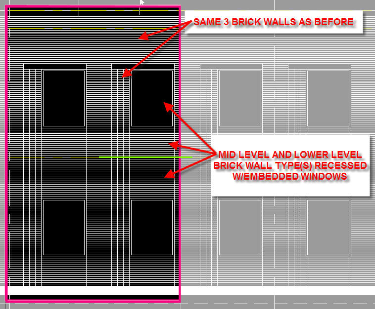
Store Front in Brick

Here we move into a more typical basic wall type. However even though the first reaction might be to make one single wall from ground to roof, we have found that it is typically easier to break walls up into seperate parts. In this case the horizontal lines represent where the wall is going to be broken up. Starting from the top there will be a "parapet" wall type, next will be a "mid level" wall type, and last will be the "lower level" wall type. There are several good reasons for doing this.
a) expeience has shown that in many cases walls that span multiple levels cause more problems then they solve due to wall join conditions (specically single level walls intersecting near to each other at different levels)
b) the lower level wall can include the base/water table as an integral sweep or split layer. Split layers are preferable, as the bottom can be un-locked, allowing the base level to be the first floor, but the base can easily be extended down for changes in grade, etc.
c) the parapet wall is really a different construction from your typical wall construction. If you really wanted to take this a step further, there would be another wall type for above the ceiling line. This wall type would might not include an interior finish, etc.
The storefront (yellow) is identical to the storefront that is nested in the metal panel, so the same pieces will be used here as well. In fact the embedded storefront can be grouped, making it very easy to quickly copy (and modify) the storefront down the length of the building. As a group, if you modify one (adjust mullion location, panel type, etc) they'll all change!
The next piece is the header (in green), this wil probably be a custom wall hosted family of some type, that gets inserted into the wall.
The last, and trickiest piece is the area in magneta. This is three columns of stacked bond brick, with each row recessed. We're not sure yet if this will be done with wall types, or a custom family of sometype. We'll have to see what seems to work best.
Curtain Wall
Not much to say here, except that some of the same pieces used in the storefront systems will be used here.
This project had the elevations drawn in ACAD, by the designer (base on Revit elevations).
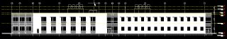 Under closer inspection, the elevation can be broken down into 4 seperate zones.

We can then figure out how we think we might model these 4 zones in revit, essentially planning and to a certain extent desiging the wall system(s).
Metal Panel

Here we planned on a dual system. The primary wall is supposed to be metal panel (grey) with stud backup. To acheive this, curtain wall will be used with a thin mullion recessed to create the joint lines. Behind the C.W. system will be a basic wall with; insultation, sheathing, studs, interior finish.
Nested in the metal panel C.W. as a panel will be another C.W. with glazed (L. Blue), spandrel (D. Blue), and custom louver (yellow) panels.Openings will have to be cut in the stud back up wall, and custom mullions will need to be used on the nested C.W. for where the glazed portions occur.
Custom mullions must be used on the nested curtain wall, otherwise it is not possible to offset the storefont mullions correctly from the metal panel "mullions". This is a known issue that Autodesk is working on. The openings in the stud back-up wall are going to be created with custom window families.
Store Front in Brick

Here we move into a more typical basic wall type. However even though the first reaction might be to make one single wall from ground to roof, we have found that it is typically easier to break walls up into seperate parts. In this case the horizontal lines represent where the wall is going to be broken up. Starting from the top there will be a "parapet" wall type, next will be a "mid level" wall type, and last will be the "lower level" wall type. There are several good reasons for doing this.
a) expeience has shown that in many cases walls that span multiple levels cause more problems then they solve due to wall join conditions (specically single level walls intersecting near to each other at different levels)
b) the lower level wall can include the base/water table as an integral sweep or split layer. Split layers are preferable, as the bottom can be un-locked, allowing the base level to be the first floor, but the base can easily be extended down for changes in grade, etc.
c) the parapet wall is really a different construction from your typical wall construction. If you really wanted to take this a step further, there would be another wall type for above the ceiling line. This wall type would might not include an interior finish, etc.
The storefront (yellow) is identical to the storefront that is nested in the metal panel, so the same pieces will be used here as well. In fact the embedded storefront can be grouped, making it very easy to quickly copy (and modify) the storefront down the length of the building. As a group, if you modify one (adjust mullion location, panel type, etc) they'll all change!
The next piece is the header (in green), this wil probably be a custom wall hosted family of some type, that gets inserted into the wall.
The last, and trickiest piece is the area in magneta. This is three columns of stacked bond brick, with each row recessed. We're not sure yet if this will be done with wall types, or a custom family of sometype. We'll have to see what seems to work best.
Curtain Wall
Not much to say here, except that some of the same pieces used in the storefront systems will be used here.

Brick Wall with punched windows
This wall will follow the same strategies as the other brick wall. Except the punched windows will either be an embedded C.W. system or actual window families. Depends on how the team wants to schedule the units. The only difference is that there will need to be additional pieces of brick wall recessed with the windows, the walls will be split at the floor level similar to the primary brick wall pieces.
I hope you find this helpful. This is a worthwhile exercise even if the whole team knows Revit, and the project is already started. It doesn't take very long either, in this case we came up with this in 30-45 mins over the phone, with screen sharing.
The exercise helps to establish what wall types need to be created, custom families required, and exposes problems that might come up. I have typically found that often times, if Revit is having a problem with constructing a condition, then it is probably a condition where you as the architect will need to pay attention to the detailing. Even in this case there are a couple of conditions where the team doesn't know exactly what they're going to do, but some ideas have already been developed.
Look for another posting next week, and thanks for reading!
-R
p.s. wanted to call attention to a great post here at: Revit in Plain English
Thursday, June 29, 2006
You "eyedeed it" now how do you find it?
Just had to quickly add to Steve's 6/28/06 post about using the Element ID tools. Select by Id can be really helpful when tracking down the causes and casualties of error messages. However one might ask how do I find one little element in a building? Revit will try to automatically find the "best" view to see an element, but as we know from experience Revit doesn't always pick a very good view, and quite often in large models, it just gives up.
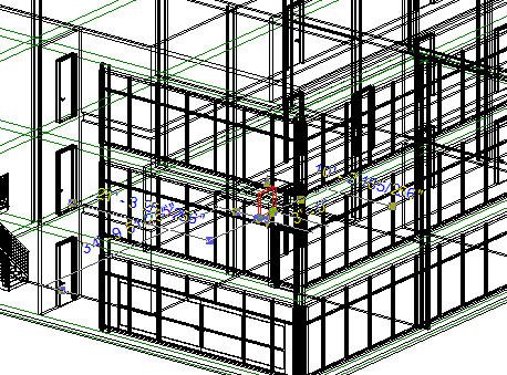
My favorite way to find elements is to open a default 3D view, and turn it to wireframe mode.


Then I do my select by ID operation. This will at least help me narrow down where in the building the element is, because it should be the only "Red" (default selection color) thing in your view of crazy lines of all your objects.

From there you should be able to spin & zoom to narrow down where the element is, and you can do an isolate if you want to, to be able to see the element only.
My favorite way to find elements is to open a default 3D view, and turn it to wireframe mode.


Then I do my select by ID operation. This will at least help me narrow down where in the building the element is, because it should be the only "Red" (default selection color) thing in your view of crazy lines of all your objects.
From there you should be able to spin & zoom to narrow down where the element is, and you can do an isolate if you want to, to be able to see the element only.
Wednesday, June 28, 2006
Time....
I know there are plenty of you who are visiting on a regular basis. My goal is a post a week, but this week has been a wash at work with way too many deadlines etc... I have my next post in mind, and I think it will be a pretty good one, but I need to make some screen shot captures etc... Stay tuned, and thanks for reading!
-R
-R
Thursday, June 22, 2006
E-Specs
The training in our DC office for E-Specs went very well yesterday! The team was very impressed by the in person training provided by the company. The CIO came down to do the training, by all reports, he and his team back at the company are very talented Revit users as well as spec writers. The general feeling by the team is that E-Specs is another tool that helps eliminate some of the mundane tasks that go with documenting a building, giving us more time to focus on design. The catch of course is that a program like E-Specs requires disciplined and careful modeling in Revit (garbage in, garbage out). The training took the team through role playing exercises using Revit, to simulate the processes of extracting specification information out of a Revit model to generate an outline spec, and then updating the specification once it has been created. Apparently the next challenge that the team over at E-Specs is taking on, is developing how to put data into the Revit model from your outline specification.
Wednesday, June 21, 2006
What's New...
Nothing major to annouce.
Our DC office did training with E-Specs today & Revit. I'm looking forward to hearing an update from them tomorrow about how it all went. Based on intial reaction it sounds like it was a productive day. I will post some information about the general reaction and results as it comes in.
Our DC office is also planning on doing a targeted cost estimation exercise with an independent cost estimator based on Revit quantities. They will be using some of the practices developed by Ken Stowe from Autodesk Revit to export and tag the quantities in excel spreadsheets. I'll also update everyone with regards to those results.
We are proceeding with upgrading our active projects to version RB9, and deploying RS1 for our MEP engineers. A project kicked off this week that will make use of both products to design and document a building.
I'm also working on a presentation on best practices when creating Revit families to assure a certain level of quality and uniformity. This presentation is based on the outline family specification we've developed. I'm creating the presentation with the thought that I'll potentially present it to a larger audience outside of Burt Hill. I'm currently planning on posting a "teaser" version once it is complete.
Thanks for reading, and stay tuned for more updates!
Tuesday, June 13, 2006
Do I really want to? But I have to...
YEAH! Revit 9 is released, we can all jump for joy! New features, more improvements, better performance!
Right, that was your reaction wasn't it? You know it was, it was mine too, still is. Take a step back though...
What about that 120,000+ sq ft project, that is a big hole in the ground right now? With CIP columns poking out. That Revit file has been through alot you know, started in version 7, upgraded to 8.1, now CA is moving along nicely, the uprgade to 8 was a little sketchy, do I really want to upgrade it again to v9.x?
Quite honestly this is a question facing us, and I think that it is a question that more firms will face. We're not doing day to day designing in this model any more. Sure it is open just about every day (on one person's computer) and he modifies a few things, adds more revision bubbles, new RFI sketches, but we're not documenting the building anymore. Why should we upgrade? The new features have no benefit at this point, we've worked around all the kinks that we found in 8.1, and it is, what it is at this point, we don't have the time or money to worry about "improving it", we're trying to build it! (if you're in Philly swing by Locust & 10th, that's right, that's a rendering straight out of Revit on the construction sign.. :) )
Furthermore, there is another huge project in another Burt Hill office that is a 40 story condo tower, all done in Revit 8.1, they just finished their CD's and I know they have no interest in bringing the model into 9, in fact from what I heard, there are drawbacks in their case, because of they way they solved some problems in 8.1.
What's a subscription firm to do? Right now we're talking to AutoDesk about this, in our case we're lucky, we'll probably resolve it one way or another, but we're big (I admit that), what is a small 12 person firm going to do if they run into the same problem? AutoDesk needs to seriously consider looking into setting up a structure to resolve this issue (because I don't see it going away), I've put my word in with out contacts, now its your turn! Tell your reseller, tell your Autodesk rep, tell the support guy on the other end of the phone! The more voices the better!
But hey, 9 is just plain cool too. :) Almost got it deployed here, IT is sometimes a little slow, :)
Oh, and by the way, please scroll on down to the next most recent post and respond, I'd really like to hear from different people.
Friday, June 02, 2006
Could you please pass the "blank" family?
OK, I've avoided cheesy titles up until now, but I couldn't resist with this one.
I'm conducting an informal survey to find out what families do people reach for first? When you're getting a project started in Revit, schematic design, deisgn development, whatever phase, what families do you need first, what families are important for putting together a decent looking set of documents?
Please post a comment with your list of top families that you need every day. Please feel free to be more specific that I have been. Being reptitive also counts as I'm interested in prioritizing requests, so even if someone else has posted an item, please post again.
My list starts with the following items (all generic and not manufacturer specific):
Doors
Plumbing Fixtures & Accessories
Casework
Furniture (block diagrams)
Windows
Light Fixtures
MEP - diffusers, sprinklers, etc...
graphic scales
I look forward to everyone's reponse!
Thanks,
-R
Thursday, June 01, 2006
Special Characters in Text
Some CAD programs make it easy to insert special characters like ° or ±. I know Autocad has special key strokes for some commonly used special characters. With Revit you have to take a few extra steps to get special chacaters into Revit text (unless of course you want memorize many complex keycodes). The other advantage of this method is you have access to a pretty large variety of special characters like, ¼, ½, ¾. So you ask, how do I gain access to all these special characters! With Charcter Map, a handy little program that has been included with Windows since 3.1 These days in Win XP/2000 the best way to access Character Map is via the run command line. Go to your Start Menu, and click on "run". In the run dialog box type "charmap" and click "OK". This will bring up the character map program, a simple dialog box that displays all the charcters in the selected type style. You can then select and copy whatever characters you need, and paste them into your text in Revit (or any other program). Another quick hint, for very commonly used charcters you may want to make a list of the custom key strokes. The key stroke for a character is listed in the bottom right (if it has one), if it is listed as "alt+xxxx" then you will need to use your number pad to the right of the key board to enter the numeric code while holding the "alt" key.
Hope this helps, cheers,
-R
Hope this helps, cheers,
-R
Wednesday, May 31, 2006
First RFI's from First Draft Family Spec
We sent out 3 families specified using our new outline spec to a contract firm. We recieved their first pass at creating the families, and additional questions/clarifications. In general we are happy with what we have received. There are a couple of instance where they either did not carefully read the specification, ignored it, or mis-understood. There were several more instances however where we either did not clearly write our spec, or we had contradictory information, or we assumed that certain assumptions would be made, and didn't give as much detail as was needed. Particular areas that we missed on; neglecting to specify the name of the .rfa file (we felt kinda foolish about this :) ), not giving enough examples regarding a naming convention, so they literally adopted the one example, failure to explain that rendering material parameters should be attached to some geometry, and perhaps biggest of all, we realized that even though we make mention of sub categories, and our master sub category list, we need to include a part in the outline spec that deals specifically with sub categories, and how and when they should be assinged to objects or pieces of an object.
In general the modeling, and parametrics were acceptable in the families. One interesting thing though, with regards to one of the specified families they took an approach completely opposite of how I created the same family. In general, we feel that my method for creating the same family allows for better performance, and more flexibility than their method. So we are going to attempt to convey that we don't want to be in the posistion of telling them exactly how to model a particular family, however there are "best practices" that we need them to take into consideration when creating a family. This is particulary tough, as there is not really a way to specify something like that, without laying out exactly how you would like to have a particular family created. We are still waiting for the results of the third family we specified, which was a dynamic parking ramp that includes transistions. This a complex family from the standpoint of some of the parametrics and formula writing, so we are curious to see what they come up with.
In general the modeling, and parametrics were acceptable in the families. One interesting thing though, with regards to one of the specified families they took an approach completely opposite of how I created the same family. In general, we feel that my method for creating the same family allows for better performance, and more flexibility than their method. So we are going to attempt to convey that we don't want to be in the posistion of telling them exactly how to model a particular family, however there are "best practices" that we need them to take into consideration when creating a family. This is particulary tough, as there is not really a way to specify something like that, without laying out exactly how you would like to have a particular family created. We are still waiting for the results of the third family we specified, which was a dynamic parking ramp that includes transistions. This a complex family from the standpoint of some of the parametrics and formula writing, so we are curious to see what they come up with.
Wednesday, May 24, 2006
Revit Standardization: Family Specs
So its been awhile since I've created a post... Architecture is like that, it tends to suck up your time. :)
The good news is that we've done some very interesting things recently. We've written an in house specification for family creation. It is written in the same way as an outline spec for building design and construction. There are numerous "fill in the blanks" where information specific to the family you need can be filled in by the spec writer. In this way we are able to assure a certain level of quality and uniformity for any family created across our 7 office (600+ person) firm. The plain spec is only 4 pages, obviously depending on how much an author writes, it could get much longer. As an accessory to the spec document we've also created an excel table where the spec writer can define all the parameters that they know they want or require, as well as the types to be defined and the settings for each parameter per type. We also expect anyone writing a spec to include sketches & other graphical information to illustrate the intent of the family. We plan to use this specification as a means for having new content created on a contractual basis. That said, already from personal experience in using the spec, it is a great tool to help define and figure out a family before you even put cursor to Revit desktop. :)
Another interesting project we have on-going is matching Revit graphic standards to our 2D CAD standards. Currently our firm has a very thorough 2D CAD standard implemented for both Microstation 2D and AutoCad, the standards are so thorough that we have a complete custom layer/level set, complete custom line styles, and custom line weights, and, on top of all that we get reliable output from both programs that looks alike, even on all the different printers our various offices own, from 8.5" x 11" to 42" B&W plotters!
That said, our custom tools in ACAD & M-station both use a replicated CSV file to define our layer set and the various attributes defined "by layer". This was fine in the 2D CAD world, however we have now introduced a new guest to the party, Revit. Revit is rather unique in the fact that it has two line weight tables (one of which has multiple line weights by scale) and as we all know it has categories and subcategories, which for the purposes of 2D DWG output, must be mapped to various layers. To that end we are going to create a database that essentially allows us to set-up all the necessary translation tables, ie, categories and subcategories to layers, layers line patterns and weights to various categories and subcategories as appropriate, and our custom line weights to Revit line weights. This database will also have the advantage of allowing us to track all of our custom subcategories, which will aid in writing the previously mentioned family specification. We also expect that the new Database will help as we begin to implement both Revit Structural & Systems.
Quite a bit to wrap one's head around, but when attempting to implement a program like Revit in a firm our size, there are a number of challenges that get magnified. I won't even bore you with the issues of attempting to troubleshoot and help someone 400 miles away, as well as simply capturing knowledge and talent, and having it shared and available across the whole firm.
Thursday, April 27, 2006
3D for everyone! & Max Renderings look good
Google has released a free version of Sketch-Up, called Google Sketch-Up. There is still a pro-version with some higher end features, but if you just want to get into 3D modeling, this is a great place to start. Try it here;
http://sketchup.google.com/
I received progress renderings from the outside rendering consultant that I sent an exported Revit model to. The renderings look good, and I have not heard about any major problems with the model from the firm. I created a custom layer export table where I put major building components on clearly named layers, like "curtain wall panels" or "mullions" rather than the 2D CAD layer naming standard that we usually employ. I assume this helped the rendering team with applying materials in 3DS Max, as it allows users to isolate geometry by layer.
Wednesday, April 19, 2006
Not Much New
Haven't done very much recently. I've converted our standard 2D Line Styles to a set of Revit Line Patterns, the next step will be to match object style's default line thicknesses to the line thicknesses assigned in our 2D CAD standard layers.
I recently saved a Revit Building file off as a solids dwg file and sent it to a an outside rendering firm. I'm still waiting to hear back from them to see if the file is usable for exterior renderings in 3D Studio Max.
I recently saved a Revit Building file off as a solids dwg file and sent it to a an outside rendering firm. I'm still waiting to hear back from them to see if the file is usable for exterior renderings in 3D Studio Max.
Wednesday, April 12, 2006
Shared families & sloped walls
So its been a few days since I posted, but then I haven't done very much in Revit either. What I have been playing with is the shared family setting for families. Turns out that if a family is shared, and nested into another family, you can only link to the nested family's instance parameters, type parameters are un-touchable because you're supposed to use a type parameter to allow the user to choose a different type of the nested family. In theory this sounds great, but there is one minor problem that comes along with this concept. In my case I've been working on baseline generic casework families, starting with a whole kit of casework parts; doors, panels, shelves, hardware, etc...
So what's the problem you ask? Well, if make a generic base cabinent with 2 doors, I probably want those doors to resize with the cabinent automatically. Great idea you say, however then you tell me that you want to schedule those doors separate from the cabinent, so that means I need the doors to be a nested shared family. Well then, I can't do both, the only way to do both would be to make all the physcial dimensions of the doors instance based parameters, which kinda defeats the purpose of having different door types. I would be willing to do this if it were possible to swap one door family for another, say if you wanted to evaluate different door styles, like a flush, paneled, or glass, but that kind of nested family swapping isn't supported yet, so it really doesn't make very much sense.
On another note, using a very small mass element in my project I very handily and very quickly made this slab wall that is supposed to slope out as it goes up, it works great! Mass elements can be very useful for unique conditions as they allow you to "cheat" when it comes to some unique situations regarding walls, roofs and floors.
Friday, April 07, 2006
Google Earth & Casework
So, two things I worked on yesterday...
I spent a better part of my day getting a google earth topo surface & image into my Revit model as an underlay for rendering. The amazing thing is, that after 4 CAD programs & G-earth everything still scaled out correctly with only a minor margin of error (minor when talking about a mile long image). I imported our site plan from Microstation into sketch-up, into which I took a 2D & 3D G-earth snap shot. Using those items in sketch-up I built some of the content buildings (dumb masses), and then export the whole thing to dwg. In autocad I did some purging and a little clean-up. In Revit I created a new generic family and dropped the dwg into the family. Since the various "parts" of the context dwg file were all on separate layers, in a Revit project it is possible to assign rendering materials to each layer of the imported dwg. The real trick was mapping the high res google earth snap shot I saved as a jpeg to the imported object. There were a few things in hind sight that I could've done to make my life easier, but suffice is to say it came down to knowing how large the photo was in the real world (ie about a mile) and figuring out the angle of rotation of the image. After that the toughest part was adjusting the offset of the "texture" to align with the geometry in Revit. In the end it worked out really well, I would share images but I'm not sure the boss would appreciate that at this point (sorry).
As to casework, I'm developing generic parametric casework families for our firm, and I'm using nested families, the weird thing is that one of my nest families, I can't link to any of the parameters, I haven't investigate further yet, but its just weird. I've seen this a couple times before and solution in the past was to make some or all the parameters instance instead of type. I'm not sure why that works, and I haven't tried yet in this case, but its just odd.
Thursday, April 06, 2006
First Post
So, welcome to my blog if you're reading it. As the title indciates this blog will be about the Software Product called Revit. www.revit.com.
In any case this blog will be more stream of conscience, then actual thought out "posts". I will try to update it on a regular basis, as I hope to use it as a journal of my work with Revit.
Just a short note about myself: I graduated from RPI with a degree in architecture, and now work in a 500+ strong firm. We are working on standardizing and implementing Revit as our software of choice for architecture and MEP (in the future). I'm heavily involved with this work, and as such I hope to use this blog to record to a certain extent "best practices" and tips & tricks.
If you're curious about the name of my blog, dig up an old copy of Arch Record from about 1999 or so, and look for a full page add from a competing software company. :)
Cheers!

Subscribe to:
Posts (Atom)


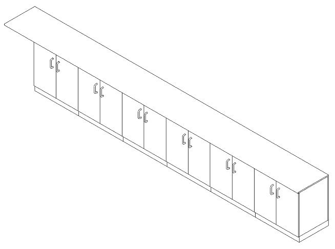